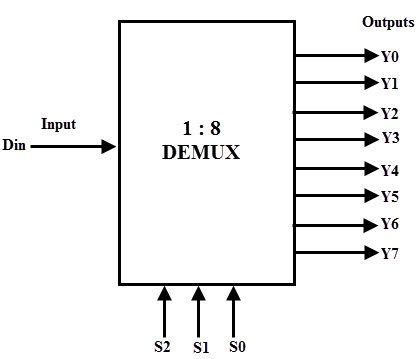
DMux8Way Chip
1. DMux8Way Chip
An 8-way Demultiplexor chip outputs the given input to certain output pin, which is specified by selector bit.
2. Truth Table
| in  | sel[2] | sel[1] | sel[0] | a  | b  | c  | d  | e  | f  | g  | h  |
|-----|--------|--------|--------|----|----|----|----|----|----|----|----|
|  0  |   0    |   0    |   0    |  0 |  0 |  0 |  0 |  0 |  0 |  0 |  0 |
|  0  |   0    |   0    |   1    |  0 |  0 |  0 |  0 |  0 |  0 |  0 |  0 |
|  0  |   0    |   1    |   0    |  0 |  0 |  0 |  0 |  0 |  0 |  0 |  0 |
|  0  |   0    |   1    |   1    |  0 |  0 |  0 |  0 |  0 |  0 |  0 |  0 |
|  0  |   1    |   0    |   0    |  0 |  0 |  0 |  0 |  0 |  0 |  0 |  0 |
|  0  |   1    |   0    |   1    |  0 |  0 |  0 |  0 |  0 |  0 |  0 |  0 |
|  0  |   1    |   1    |   0    |  0 |  0 |  0 |  0 |  0 |  0 |  0 |  0 |
|  0  |   1    |   1    |   1    |  0 |  0 |  0 |  0 |  0 |  0 |  0 |  0 |
|  1  |   0    |   0    |   0    |  1 |  0 |  0 |  0 |  0 |  0 |  0 |  0 |
|  1  |   0    |   0    |   1    |  0 |  1 |  0 |  0 |  0 |  0 |  0 |  0 |
|  1  |   0    |   1    |   0    |  0 |  0 |  1 |  0 |  0 |  0 |  0 |  0 |
|  1  |   0    |   1    |   1    |  0 |  0 |  0 |  1 |  0 |  0 |  0 |  0 |
|  1  |   1    |   0    |   0    |  0 |  0 |  0 |  0 |  1 |  0 |  0 |  0 |
|  1  |   1    |   0    |   1    |  0 |  0 |  0 |  0 |  0 |  1 |  0 |  0 |
|  1  |   1    |   1    |   0    |  0 |  0 |  0 |  0 |  0 |  0 |  1 |  0 |
|  1  |   1    |   1    |   1    |  0 |  0 |  0 |  0 |  0 |  0 |  0 |  1 |
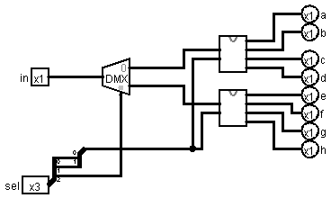
3. Implementation (Logisim)
Representation of the DMux8Way Chip in the logisim software using the previous gates.
4. Implementation (HDL)
Representation of the DMux8Way Chip in HDL using previous gates.
CHIP DMux8Way {
    IN in, sel[3];
    OUT a, b, c, d, e, f, g, h;

    PARTS:
    DMux(in=in, sel=sel[2], a=abcd, b=efgh);
    DMux4Way(in=abcd, sel=sel[0..1], a=a, b=b, c=c, d=d);
    DMux4Way(in=efgh, sel=sel[0..1], a=e, b=f, c=g, d=h);
}